How to design gearmotors for extreme ambient conditions
- Wednesday - 01/04/2020 10:06
- Close page
Following some straightforward advice on gearmotor design will help ensure your gearmotor works in the most extreme environments. Designing a gearmotor application is tough enough in more or less “normal” conditions, normal here meaning something like room temperature and stable or typical humidity and altitude.
Throw that application into an extreme environment and the design gets more complicated. But it doesn’t have to be. For anyone designing a gearmotor application in extreme ambient conditions, there are some guidelines that when adhered to will help ensure that the design succeeds.
First, the basics
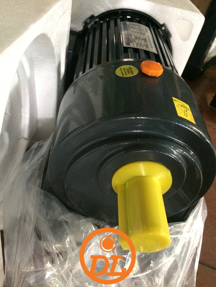
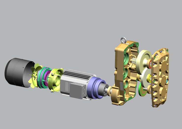
A gearmotor is a combination of a gear reducer and an electric motor. The two most important factors at the gearmotor output shaft are its rpm and torque. A right angle, straight or parallel shaft gearbox can be combined with a permanent magnet ac, ac induction, or brushless dc motor.
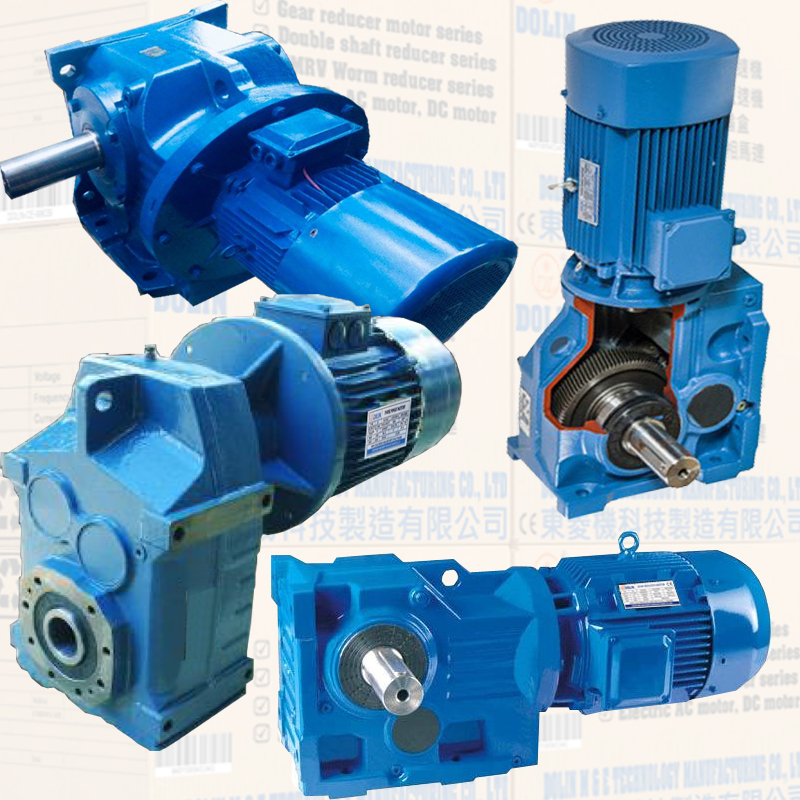
The gearmotor applications discussed here are not exposed to high-pressure water spray, such as in freezers, unheated facilities or enclosures. They’re used in applications such as forklifts and electric vehicles, lifting technology, construction equipment, packaging machinery, as well as dockside crane hoists, and trolley and bridge drives, among others.
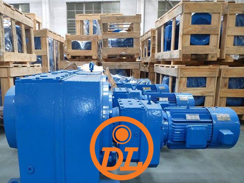
The goal is to have the gearmotor operate for decades of exposure to extreme ambient conditions with low maintenance because they may not be easily accessible. There’s not much mechanically different in a gearmotor for extreme temperatures and altitudes; mainly it’s lubrication, duty cycles, heating or cooling considerations and construction materials selection. So these tips can be used to upgrade existing systems as well.
The typical types of gearmotors we’re talking about include hoist drive gearmotors, which lift loads between 3.2 and 40 metric tons. They are powered by a 2.5 to 38 kW asynchronous cylindrical-rotor motor with 3-stage parallel shaft gearboxes for lifting speeds of 4 to 8 m/min at drum diameters of 140 to 405 mm and 4/1 reeving. Typical pole-switching motors (8/2-pole) are used. Variable speeds are programmed with inverters for acceleration and deceleration ramps with extremely slow start and braking which minimizes load swings.
A good start is to review data on past extreme temperature conditions in which the application will be operating and any other unique conditions that may be relevant to the design. In the following sections we’ll cover temperature, altitude and humidity and the way these factors influence gearmotor selection.
Temperature
What happens to the gearmotor when the temperature drops to -40 C?
From -40˚ C (-40˚ F) to +60˚ C (+140˚ F) a meter of ductile iron expands 0.123 mm. That’s the temperature range we’ll be covering here.
Altitude is the other extreme we’ll be covering. For an internal combustion engine, the general rule of thumb is a 3 to 4% power loss for each 1,000 feet above sea level. So a 300 hp car at 10,000 feet would lose 30 to 40 hp. Less density means less compression. Less actual matter in the atmosphere (oxygen, nitrogen, and argon mostly) is being drawn into the cylinders, and therefore compression is less. For a gearmotor, that means less atmosphere to dissipate heat.
How to compensate for temperature extremes? (A standard temperature range is -20 to +40° C.)
A common extreme temperature swing is when a forklift moves from a -30˚ C freezer to a +40° C dock door. For both extremely cold (-40˚ C) to very hot conditions (+60˚ C) you’ll need to address the following.
Gearbox oil – Synthetic lubricants are used when mineral oils have reached their performance limit for frequent starts and stops, high loads, system shocks, low or high-temperature service, extended oil service interval requirements and reduced internal friction besides reduced operating temperatures. They also operate at higher temperatures without losing viscosity, forming residues and offering resistance to foaming.
Petroleum products begin to degrade at or below +100°C, whereas synthetic hydrocarbon lubricants function well to +125°C. Synthetics offer extreme low-temperature advantages as well. They also have lower vapor pressures than petroleum products, an important factor in ensuring that the lubricant doesn’t break down. The chemical homogeneity of synthetic lubricants results in greater load carrying capacity, higher viscosity indexes, better lubricity, greater efficiency and extended serviceability than their petroleum-based counterparts.
Shaft seals – If the gearmotor remains at low temperatures for extended periods of time, upgrade motor shaft seals to NBR (elastomeric) material or use high-grade grease for shaft seal lubrication. Elastomeric materials are composed of a polymer, filler, processing aid, protectants, and curing agents.
Many times standard oil seals are made of Nitrile or rubber and are rated for temperatures up to +125˚ C. If ambient or oil temperatures rise above this level, you will have to use higher performance materials.
Motor cooling fan – These should be made of aluminum, GGG (nodular iron) or special plastic material.
For proper function and use in temperatures from -20° to -40°C
Housings – Switch end shield material from GG (grey cast iron) to GGG (nodular iron). Nodular ductile iron possesses high strength, ductility and resistance to shock. Annealed nodular ductile iron can be bent, twisted or deformed without fracturing. Its strength, toughness and ductility duplicate many grades of steel but have low-cost casting procedures similar to gray cast iron.
Ordinary gray cast iron has a random flake graphite pattern. Nodular ductile iron has a few hundredths of a percent of magnesium or cerium in its formula causing the graphite to form in small spheroid “nodules” rather than flakes. They cause fewer discontinuities in the structure of the metal for a stronger, more “ductile” iron. You can also use aluminum if allowable stress is not exceeded.
Rotor shaft – Switch material from 1045 steel to alloy steel, e.g., 42CrMo4 or similar. 1045 is a low hardenability carbon steel with a typical medium tensile strength range of 570 to 700 Mpa or Brinell hardness range of 170 to 210. It’s characterized by fairly good strength and impact properties. 42CrMo4 Alloy Steel is chromium-molybdenum steel with high strength and hardenability. It has high fatigue strength and good low-temperature impact toughness.
Motor heating – This could be a heater jacket, motor heating bands or the winding could be powered to maintain a certain temperature (this is also used to prevent moisture build-up in high humidity environments). External heating jackets, covers or housings are often installed by crane builders because they also need to protect the gearbox and other components.
Junction Boxes – Switch from plastic to aluminum
Fan Shroud – Switch from plastic to sheet metal version
Brake Design – Completely enclosed instead of open design
De-rating Torque – It might even be necessary to de-rate the maximum acceptable gearbox torque or use a larger gearbox.
For proper function and use in temperatures from +40° to +60° C
Note that temperatures above this must be reviewed on a case by case basis and cannot be covered by simply changing certain components.
If the gearmotor is mounted inside an enclosure near combustion engines or other systems that generate heat or are exposed to direct sunlight, it will require internal motor components that have higher temperature ratings. High ambient temperatures can also negatively impact motor torque and direct sunlight will degrade sealing components.
Junction Box – Switch from plastic to aluminum
Fan Shroud – Switch from plastic to sheet metal version
Altitude
For proper function and use at high altitudes
Heat dissipation on the surface of motors and gear units decreases with altitude. The thermal performance is reduced due to thinner air. Typically rated installation altitude is a maximum of 1,000 m above sea level. For higher altitudes, you should consider the following.
Verify the actual duty cycle of your application and ask yourself is a continuous duty motor really needed here? If it turns out that the application requires the same duty cycle as the rating of a motor at 1,000 m above sea level you can install a larger motor or add forced-air cooling to compensate reduced cooling capacity provided by the thinner air. In many cases, it makes sense to discuss possible options with the motor OEM.
A word about duty cycles
Duty cycles do not only impact the motor performance rating, e.g., a continuous duty cycle S1 motor will provide a higher output if it’s used at an S3 intermittent duty cycle, but also especially for gearboxes used in extraordinary applications where torque peaks and system shocks are possible. For such situations, it’s critical to carefully determine what duty cycle and what peaks/shocks per a specific time period are experienced so the engineering team of the motor/gearbox OEM can select and recommend a suitable drive system.

So even if the application does not have a high rated torque and duty cycle requirement, other operational factors could result in the need for a much larger and stronger geared motor to be required to assure a satisfactory service life. And as a final word, always inform the motor OEM if your application is being used in extreme ambient conditions – this can be a game changer.
More information about recommended service lives for different applications have been published by the American Gear Manufacturers Association (AGMA.) These duty cycle recommendations have been determined from the experience of many gearmotor manufacturers. AGMA standard 6009 lists many applications by a service class (I (1 to 1.39), II (1.40 to 1.99), III (2 and above)) with class I being the simplest applications and class III being the hardest. Typically the total duty cycle for an application will take into account ambient temperature, cyclic duration, mass acceleration, operating time, and cycles per hour.
How to determine duty cycle
First, you need to establish a target life. Not the calendar time, but the operating time. You need to know the duty cycle of the application during operation, and the number of hours the machine operates during the day.
As an example; a gearmotor drives a conveyor in short bursts, 2 minutes at a time, with 2 minutes off before repeating, over and over, during two 10-hour shifts, five days a week. You need it to operate trouble-free for at least five years or 13,000 hours.
Service life is 25,000 hours nominal with a 1.0 service factor, based on an AGMA standard. 25,000 hours is a nominal figure, so 50% won’t last that long. Use L10 life ratings, which means that 10% of the gearboxes operated at that load are expected to fail before the L10 life, and 90% are expected to last longer.
So a gearbox with a nominal life of 25,000 hours would have an L10 life of 5,000 hours. According to AGMA guidelines, a conveyor not uniformly fed and operated more than 10 hours a day should have a 1.50 service factor. A similar calculation will need to be done for the motor.
Humidity
The most common system used to classify a product’s intrusion and water resistant compatibility is the IP rating, which is published by the International Electrotechnical Commission (IEC). (IP stands for International Protection, but is sometimes referred to as Ingress Protection.) Today, ac induction and permanent magnet ac motors typically meet protection classes IP54 or 55 and with certain steps can even satisfy IP65 or 67 demands. So the IP ratings do not properly provide protection for high humidity environments and other steps are necessary to protect the gearmotor.
To prevent corrosion, protect all bare metal surfaces. Also, motor laminations should be painted. Use a continuous low voltage and current power supply to your winding to prevent condensation when the motor is not in use. For brakes, all wear surfaces must be stainless steel and sometimes a completely enclosed outdoor brake is the best solution.
Feedback and improvement
Life Cycle Cost analysis is a management tool that can help companies minimize waste and maximize energy efficiency for many types of systems. A complete understanding of everything that makes up the total cost of a system throughout its lifespan provides an opportunity to reduce energy, operational and maintenance costs.
Analyze each element of the life cycle and determine a realistic value for use in computing the total life cost, including purchase price; installation and commissioning cost (including training); energy costs; operation costs; maintenance and repair costs; downtime costs; environmental costs (disposal of contaminant liquids and contaminated used parts, such as seals); and decommissioning/disposal costs (including restoration of the local environment and auxiliary services.)
In addition to supporting a design decision, the LCC analysis can be used to reflect changes in scope, schedule or application. The process can become a valuable tool for continuous improvement.