


- Home
- /
- News
- /
- Dolin News
How to Wire AC Gear Motor
Generally, AC torque motors adopt cage rotor structures and increase the pole logarithm to get the low speed. They mainly operate in high load, low speed state, and can also run in stalled state in a short or long term.
In this working environment, the motors provide a stable torque and also reverse torque (brake torque) to the load. The shaft of the torque motors output power not at a constant power but at a constant torque.
A speed reducer (gearbox) is a component consisting of gear drive, worm drive, and a gear-worm drive which are enclosed in a rigid housing. It is usually used as a gearing between the driving link and working machine. As it plays a great role in matching revolution speed and transmitting torque between driving machine and work machine/actuator, speed reducer is widely used in modern machinery.
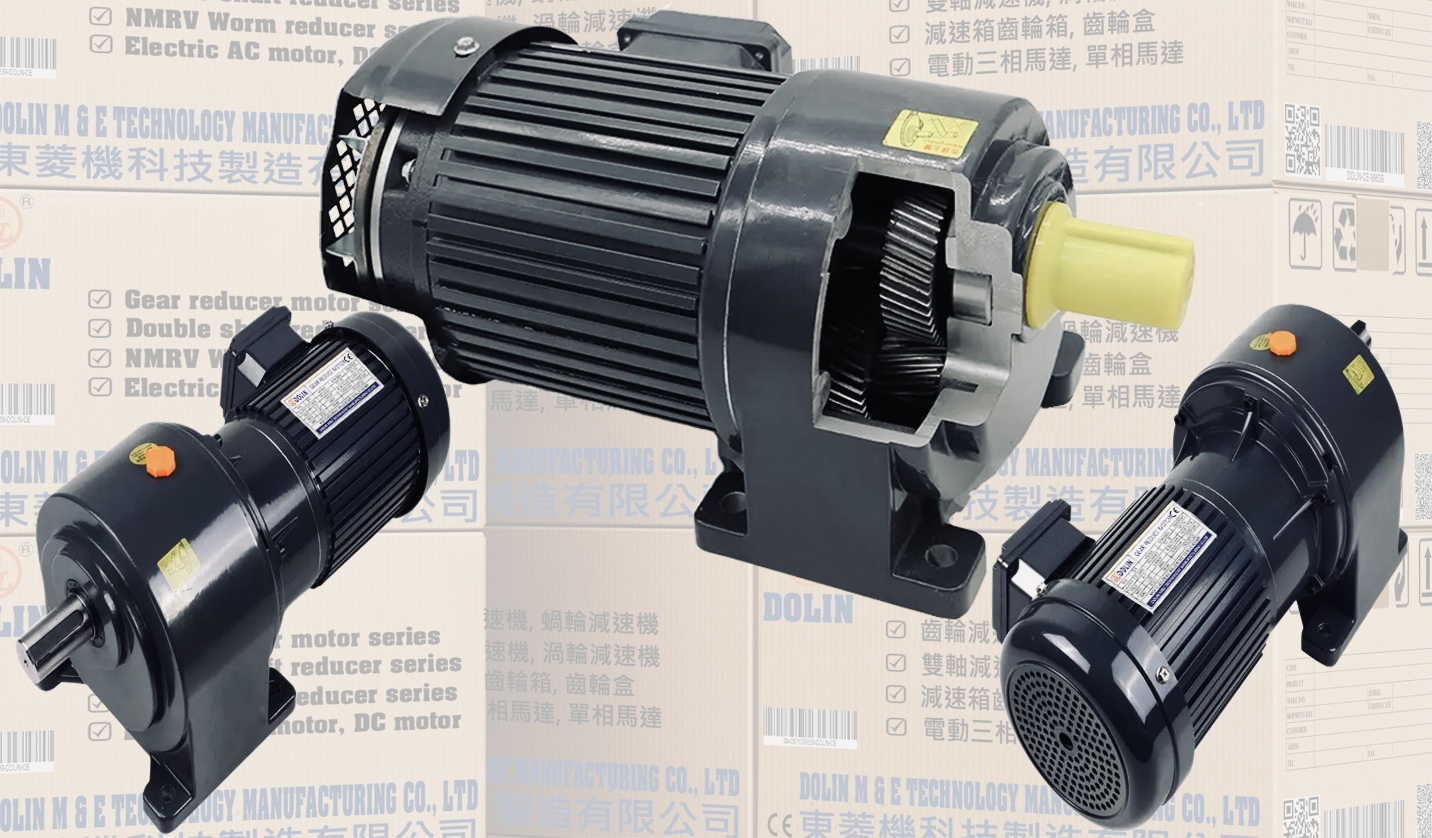
ATO AC gear motor is composed of a single phase AC torque motor and a gearbox, which has high starting torque and sloping characteristics, allowing speed control simply by changing the voltage of the power supply. The special rotor provides excellent performance for holding, winding, andtensioning applications. Next, we will introduce how to wire and test a ATO AC torque motor with gearbox?
AC torque motor specifications
The specifications of the torque motor used for testing are as follows:
Rated Power:6W
Frequency: 50Hz
Rated Voltage: 220V AC
Rated Speed: 1250 rpm
Gear Ratio of the Gearbox: 15:1
If you purchase this 6W gear motor, a capacitor of 0.8μF is attached.
Gearbox has three wires, a red wire, a blue wire and a white wire, and the capacitor will be connected to the blue wire and the white wire. Besides, A 250V 15A switch is required to switch the direction of rotation of the motor. Once everything is ready, we can wire it according to the circuit diagram.
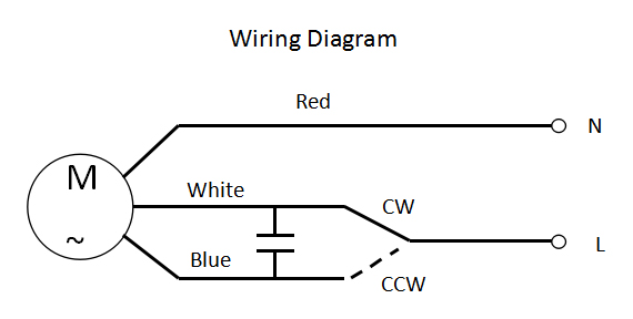
Wiring procedure
Connect the capacitor to both ends of the blue and white lines and connect to the transfer switch.
The intermediate terminal of the transfer switch is connected to the power supply.
Connect the power cord and the wiring is completed.
Power on and testing
Toggle the switch to the left and the motor rotates clockwise.
Toggle the switch to the right, the motor rotates counterclockwise.
For more detailed wiring operation please see video below. Further more, DOLIN offers 3W, 10W, 20W AC gear motors (torque motor with gearbox) for your applications as well.
Key: Vertical 3 Phase ac induction motors, electric motor, Vertical Inverter Duty motor, DC Brake motor Oil Pressure Motor, helical gear motor, AC mini Induction DC gear motor, Gear reducer motor series, NMRV NRV worm reducer series, Worm reducer series, Horizontal Inverter duty, worm gear series, ac motor, vertical gearmotor, helical horizontal gearmotor, gear reduce motor, bevel gearmotor, cyclo gear motor, NMRV gear motor, worm reducer
Newer articles
- Standard Warranty Information (21/09/2020)
- Light Duty Type Helical Gear Small AC Motor With Brake (01/01/2021)
- Vietnam Electric Motor Market is Expected to be Dominated by HVAC Application Segment Until 2028 (20/01/2022)
- How to spot a fake product (01/01/2021)
- Looking to buy a geared motor for your industrial needs? (19/09/2020)
- Selecting and Sizing Geared Motors (19/05/2020)
- Efficient integrated gearmotors power intralogistics application (18/06/2020)
- Motion Trends: Customization tops gearmotor design trends (16/06/2020)
- DC Motor / DC Gear Motor Basics (02/02/2020)
Older articles
- How to distinguish an original product from a counterfeit one (10/03/2017)
- 5 Ways Product Quality Impacts Your Brand (08/06/2018)
- The Importance of Brand Image and Brand Loyalty (14/02/2018)
- Reasons Why Marketers Need Image Recognition (10/11/2017)
- Dolin moves motor manufacturing from Taiwan to Vietnam (02/05/2017)
Join